Cheap Smart Speaker Teardown part 3 - How to find the speed of a serial port
Introduction
Last month I picked up a cheap smart speaker from a local electronics retailer and this weekend I was rained in, so took the opportunity to have some fun and practice doing a teardown and firmware dump
This is the third part in a multi-part series:
- Part 1 - Photo essay of physical teardown
- Part 2 - passive reconnaissance and integrated circuit identification
Recap
To recap, the objective is to complete a physical tear down (done), perform a black box reconnaissance (done), dump the firmware and make a preliminary attack surface analysis. With luck, then put it back together retaining access to the running internals.
The main processor I am 95% confident is an ARM processor with 512MB of DDR; there is a Bluetooth + Wi-Fi SOC with Linux drivers, and a good chance this system runs Linux. There is a DAC, a secondary microcontroller, and a 1GB flash chip. The PCB hints there is a serial port but we haven’t yet located it.
Part 3 - Serial Port
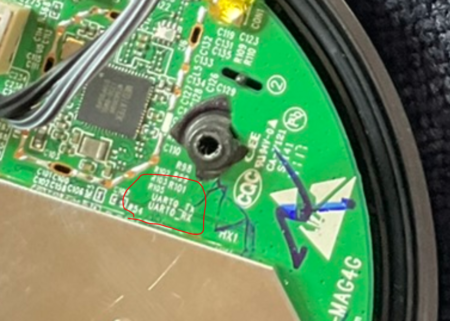
As noted in Part 1, the upper side of the PCB has labels for UART Rx & Tx. There are no obvious corresponding pins nearby!
Hypothesis - unpopulated connector
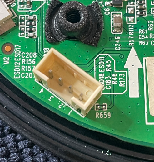
I started with that unpopulated connector. WWith the multimeter- it seemed that what I will call Pin2 was ground (it had continuity with the metal can and some other ground points), and Pin 4 was approx. 3V. As a test, when I power cycled the device, with the oscilloscope on Pin 4 you could see it warming up to that voltage, as for example a capacitor was charging.
Ultimately, I determined that the 2 inner pins (2,3) were ground, and the outside (1,4) were at ~3V3 at steady state, so I think this was an external power connector (perhaps, I’m still not 100% sure, and I spent no time trying to trace the circuitry.)
Hypothesis - check all the test points
I loaded the PCB photos in hi-res on the big screen, and spent some time eyeballing for candidates. There are not so many obvious on the top of the PCB, but the underside was covered with labelled test points.
Here is where I hit a red herring. It is very easy to make mistakes when searching for an unknown; but then, if there was already a published schematic I probably wouldn’t be needing to reverse engineer anything!
On the underside in the area of the UART labels, there are a number of pins. There are the pins marked (A), but they had no label. But I got interested because at (B) are some pins - these are marked TPD5 and TPD6 - and I noted most of the other test points were labelled TPMxx. I wondered - is the ‘D’ the difference?
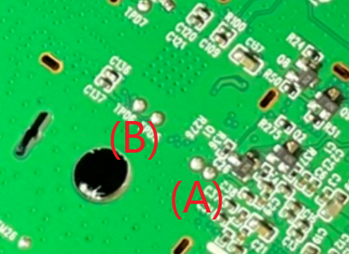
I tested all of these (and several others) with the multi-meter, but as expected, this was inconclusive. Sometimes, you can speculate that a pin might be some kind of communications pin, or active, if the voltage is “in-between”, due to continuous transmissions moving the level from the default high or low. In particular, some of these pins were solidly at ground, others at 1.8V. This device is actually 1.8V for much of its logic, not 3v3 like common Raspberry Pi board pins.
In the end, I soldered some wires to (B) and connected them in turn to the oscilloscope, whilst power cycling the device. My hope was that on boot there would be bursts of what might possibly be serial traffic.
So far, no joy. On one of them I seemed to get a nice square pulse, to high, to low, to high, but with a long duration (perhaps half a second). This did confirm the 1.8V logic level though. This could be useful as a trigger in future exercises.
That pair of unlabeled test points
Then I shook my head, because on further inspection, I realised the pins at (A) were very much directly underneath the UART labels! It was so obvious in hindsight. I removed the wires and instead soldered them to (A).
What I should have done, was taken some more square on images of both sides of the PCB, then flipped one and made them partially transparent, and overlaid them in a photo editor. I was being lazy though, and just rotating it in my hands and trying to keep note of where the labels might be…
Anyway, this time, with the CRO connected (details below), some joy - what looked like serial!
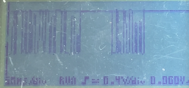
Excitedly, I connected this to the Tx/Rx lines on my Pi400, and fired up picocom set to a very common baud rate. But no joy - just junk!
pi@pi400:~ $ picocom -b 115200 /dev/ttyS0
picocom v3.1

port is        : /dev/ttyS0
flowcontrol    : none
baudrate is    : 115200
parity is      : none
databits are   : 8
stopbits are   : 1
escape is      : C-a
local echo is  : no
noinit is      : no
noreset is     : no
hangup is      : no
nolock is      : no
send_cmd is    : sz -vv
receive_cmd is : rz -vv -E
imap is        :
omap is        :
emap is        : crcrlf,delbs,
logfile is     : none
initstring     : none
exit_after is  : not set
exit is        : no

Type [C-a] [C-h] to see available commands
Terminal ready
�	�      �1�z��щ��	�	1	{����	z)
                                                          α	!��)����	a�1�z�		��	!��
Usually this junk indicates the wrong speed. So I cycled through all the common ones - 115200, 57600, 38400, 19200, 9600… just more junk. At this point I took a break and did some more searching. Maybe it was 230400? Until now, 115200 was the most common (with the exception of the ESP8266, which has a weird rate at 74880 during boot due to choice of crystal, and then switches to 57600 or whatever you put in your custom firmware)
How to us an oscilloscope to estimate baud rate
Back to the CRO: the quick description is: keep triggering until something fills the screen with a diversity of high and low of various widths, and then measure the thinnest. In this case, the pulses and gaps were approximately 1 microsecond… inverse of approximately 1MSPS, or close enough to 921000 baud… so I reconfigured the Pi again, and this time, running the command picocom -b 921000 - eureka!
Longer description of how to estimate baud rate
I have at several oscilloscopes. Young teenage me would be agape at this, at the time even a 10Mhz dual channel analogue cost some $100’s at (then popular retailer) Dick Smith Electronics. I even spent much time trying to work out how to build my own, amassing various parts, but never making any headway. Fast forward too many years, now I have a Hantek MSO (a USB connected 4-channel 100Mhz + 16channel logic analyser); a second hand 20MHz dual channel analogue; a pride of my collection, a second hand Tektronix 468 Analog ‘Digital Storage Oscilloscope’, getting a bit old now being first produced in 1984, but still a top notch piece of kit! and a handheld single channel 40MSPS digital Velleman HPS10 with a 3” 64x128 pixel monochrome LCD which must be 15+ years old now but was the first one I ever owned.
I couldn’t be bothered getting the Hantek out and connected up to a laptop, and the others are not really that portable so I decided to use the Velleman. Plus, it can be just as useful, and even fun to use the older kit instead of a modern connected digital device. Here is how you estimate baud rate with a single channel CRO like this:
- set the input to DC coupling
- set the scale to 0.4V/division, knowing we have 1.8V logic
- this will have 1.8V high level off the top of the screen, which actually doesn’t matter
- but then I also shift the x axis down, this way the signal will fill more of the screen
- set the time-base initially to 50µs/div
- this will show decently wide pulses at lower baud rates (say 57600) but still make bursts obvious at higher rates
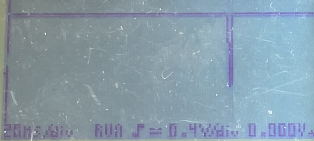
- in the beginning, when the time-base is too wide, you might get a pulse when a debug line is output:
- with the trigger on default run, if the system is regularly outputting serial then the screen should keep updating with signal
- change the trigger to run once, so it triggers on the next burst and stays on the screen
- adjust the time-base down so that the next trigger may possibly resolve the individual pulses, and try again
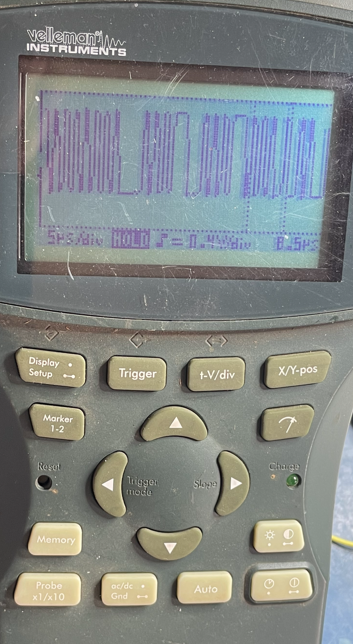
- as you narrow the time-base, you can start to see the signal resolving:

- in this case I ended up at 5µs/div which covered the screen with around 80µs of signal
- trigger again, keep triggering until the signal has a lot of narrow pulses
- the ideal data bytes for this would be 0xaa or 0x55, but we have no control over what is output in this case
- use the markers a number of times to estimate the width of several of the narrowest pulses
- and then again, to estimate the width of a bytes worth of pulses
- there is a little bit of guesswork involved, but you can get a feel for which are individual 0101 sequences
- in this case, I observed that each bit was of the order of 1µs
- and roughly typically 8.5µs wide for 8 pulses width, and don’t forget there is a stop bit
- finally, observe that 921000 baud will have pulses just wider than 1µs (strictly, 100000/921000 or 1.08µs) which rounds up to around 8.5µs (strictly, 8.68µs) for a byte
Finally, serial output
With the correct baud rate, this is what I now had on screen:
pi@pi400:~ $ picocom -b 921000 /dev/ttyS0
picocom v3.1

port is        : /dev/ttyS0
flowcontrol    : none
baudrate is    : 921000
parity is      : none
databits are   : 8
stopbits are   : 1
escape is      : C-a
local echo is  : no
noinit is      : no
noreset is     : no
hangup is      : no
nolock is      : no
send_cmd is    : sz -vv
receive_cmd is : rz -vv -E
imap is        :
omap is        :
emap is        : crcrlf,delbs,
logfile is     : none
initstring     : none
exit_after is  : not set
exit is        : no

Type [C-a] [C-h] to see available commands
Terminal ready
                   Battery voltage: 3975 mV
                                           Battery 75% ~100%
When I pressed ENTER with the other line connected as well, I had a hash (#) prompt displayed!
As an aside, even though the pi400 is 3v3 logic it had no trouble both sending and receiving the 1.8V serial signal
It did run into issues with reboot though - the device would hang if rebooted with Tx connected. Annoying if not a showstopper.
posted in embedded, hacking, reversing, repurposing, android, hardware, home-automation
subscribe via RSS
